
Description
RFID READER MODULE
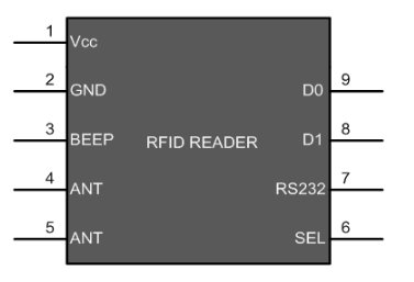
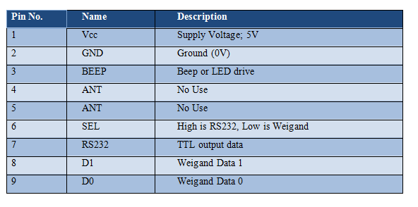
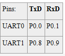
Pin Description

Control and Status Registers :
Data Related Registers :
Baud Rate Setup related registers :
Interrupt Related Registers :
Programming Steps
Application
/*  Name     : main.c
 *  Purpose  : Source code for RFID Interfacing with ARM LPC2148.
 *  Author   : Gemicates
 *  Date     : 2018-01-02
 *  Website  : www.gemicates.org
 *  Revision : None
 */
#include <lpc214x.h>      			  	       // header file for LPC21XX series
#define bit(x) (1<<x)

void lcd_init(void);
void cmd(unsigned char a);
void dat(unsigned char b);
void show(unsigned char *s);
void lcd_delay(void);

void ser_init(void);
void tx(unsigned char c);
unsigned char rx(void);
void tx_string(unsigned char *s);

int main()                                     		       // main function
{
 int i;
 unsigned char id[12];

 IO1DIR = 0xFFFFFFFF;                        		       // make PORT1 pin as Output mode
 ser_init();
 lcd_init();
 cmd(0x80);                                                    // clear screen
 show("<<SHOW UR CARD>>");
 cmd(0xc0);                                                    // bring cursor to second ROW
 for(i=0; i<12; i++) {
 id[i]=rx();
 dat(id[i]);
 }
 while(1);                                                     // Repeat(loop) forever
}
void lcd_init()                                                // Funtion to Initialize LCD
{
 cmd(0x38);                                                    // for using 8-bit 2 row mode and 5x7 Dots of LCD
 cmd(0x0e);                                                    // turn display ON for cursor blinking
 cmd(0x01);                                                    // clear screen
 cmd(0x06);                                                    // display ON
 cmd(0x0c);                                                    // display ON,cursor OFF
 cmd(0x80);                                                    // clear screen
}

void cmd(unsigned char a)                                      // Function to send command to LCD

{
 IO1CLR=0xFF070000;
 IO1SET=(a<<24);
 IO1CLR=bit(16);                                               // rs=0
 IO1CLR=bit(17);                                               // rw=0
 IO1SET=bit(18);                                               // en=1
 lcd_delay();
 IO1CLR=bit(18);                                               // en=0
}

void dat(unsigned char b)                                      // Function to send data to LCD
{
 IO1CLR=0xFF070000;
 IO1SET=(b<<24);
 IO1SET=bit(16);                                               // rs=1
 IO1CLR=bit(17);                                               // rw=0
 IO1SET=bit(18);                                               // en=1
 lcd_delay();
 IO1CLR=bit(18);                                               // en=0
}

void show(unsigned char *s)                                    // Function to display it in LCD
{
 while(*s)
 {
 dat(*s++);
 }
}

void lcd_delay()                                               // Time delay function in milli seconds
{
 unsigned int i;
 for(i=0;i<=3000;i++);
}
void ser_init()                                                // Funtion to Initialize UART
{
 VPBDIV=0x02;                                                  // PCLK = 30MHz
 PINSEL0|=0x05;
 U0LCR=0x83;
 U0DLL=195;
 U0DLM=0;
 U0LCR=0x03;
 U0TER=(1<<7);
}

void tx(unsigned char c)                                       // Funtion to transmit the data
{
 U0THR=c;
 while((U0LSR&(1<<5))==0);
}

void tx_string(unsigned char *s)
{
 while(*s) {
 tx(*s++);
 }
}

unsigned char rx()                                             // Funtion to recive the data
{
 while((U0LSR&(1<<0))==0);
 return U0RBR;
}